 Mellott's VR
VB Cart Programmer Build
Originally 9/21/18
Updated 5/30/19
This is an overview of the VB cart programmer build. For more information on the VB cart programmer itself visit its main page here. There’s a few steps in the process where I’m lacking good pictures and they’re marked accordingly. I’ll update them in the future. Lets get started!
The VB cart programmer takes about 2 hours to build per unit. That’s after some practice with the right tools. Lets start with the tools you’ll need:
1. Sharp Xacto blade
2. Soldering iron
3. Security screwdriver for VB (large and small)
4. Wire cutters
5. Wire strippers
6. 401 Loctite
7. DP100 3M Epoxy
8. 50mL Epoxy gun
The next thing you’ll need are parts:
1. 3D printed VB mini case (7 part types)
2. Red on black 16×2 LCD
3. eBay I2C to LCD backpack
4. Elegoo Arduino atmega2560 R3 board
5. VB motherboard connector
6. Custom PCB for VB motherboard connector
7. 26AWG wire (assorted colors)
8. Adafruit MicroSD card breakout board
9. Large and small VB security screws (substitute fine)
10. 30AWG solid core jumper wire
The 3D printed VB mini case and custom PCB for VB motherboard connector, you’ll need to get from me for now. I haven’t released these design files. There is a 3D regular box enclosure that does have design files released. I’ll post them here when I get a chance.
3D Parts Cleanup & Initial Assembly
The first thing to do is to clean up all those 3D printed parts. Take a Xacto blade and clean up any left overs of the 3D printing process such as support material or strings coming of the parts. It will help to do a fit check with all the parts to see what exactly needs to be trimmed. Do this for the main top and bottom VB mini larger housings, as well as the left and right ear, and the gray knob inserts.
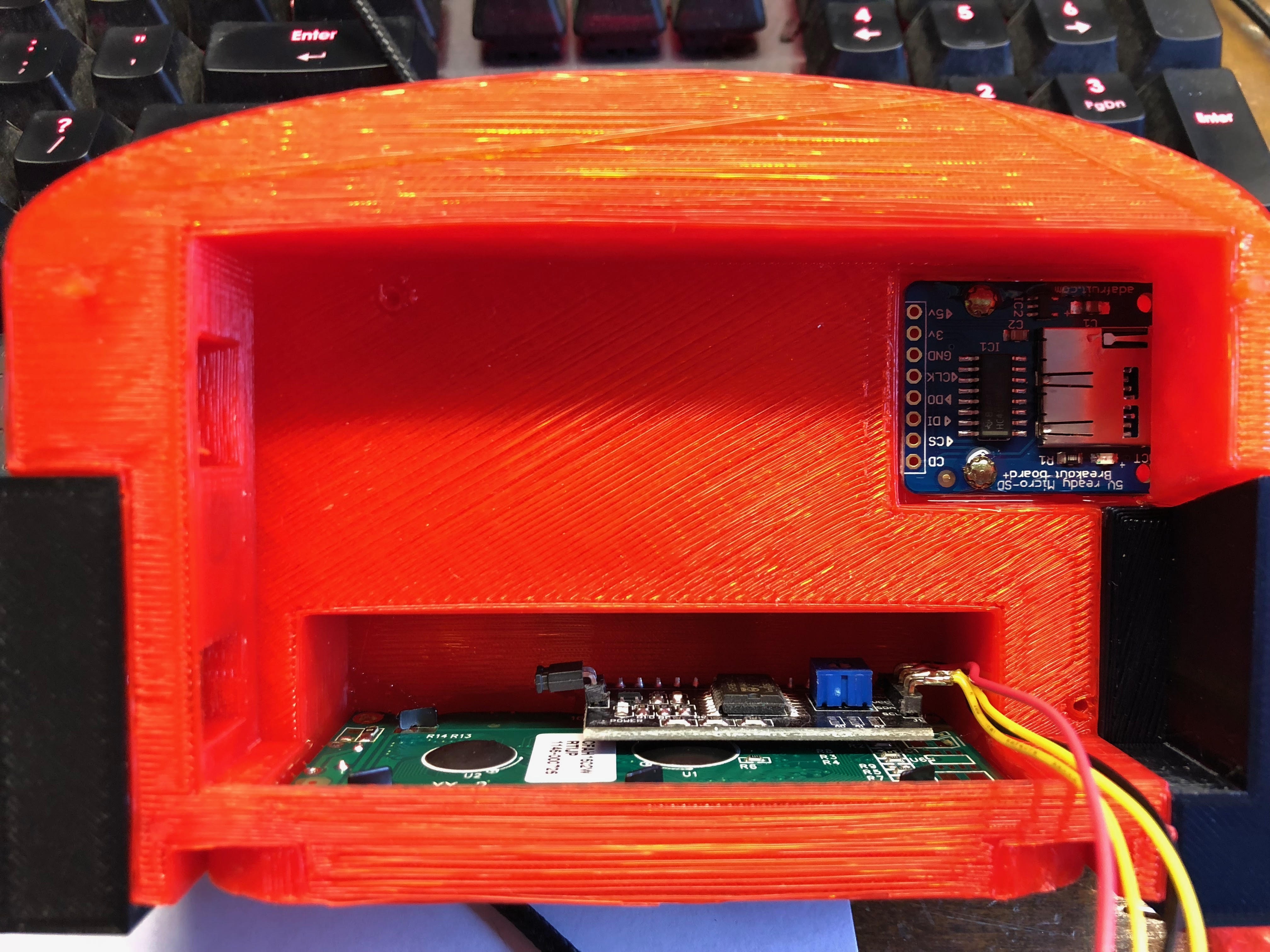
Once those parts are cleaned up, the MicroSD cart breakout board needs to be screwed into place prior to gluing some of the 3D printed parts together. I’ve built the VB mini enclosures using original VB security screws. Use 4 of the small security screws to screw the SD card board into place as shown in the picture below.
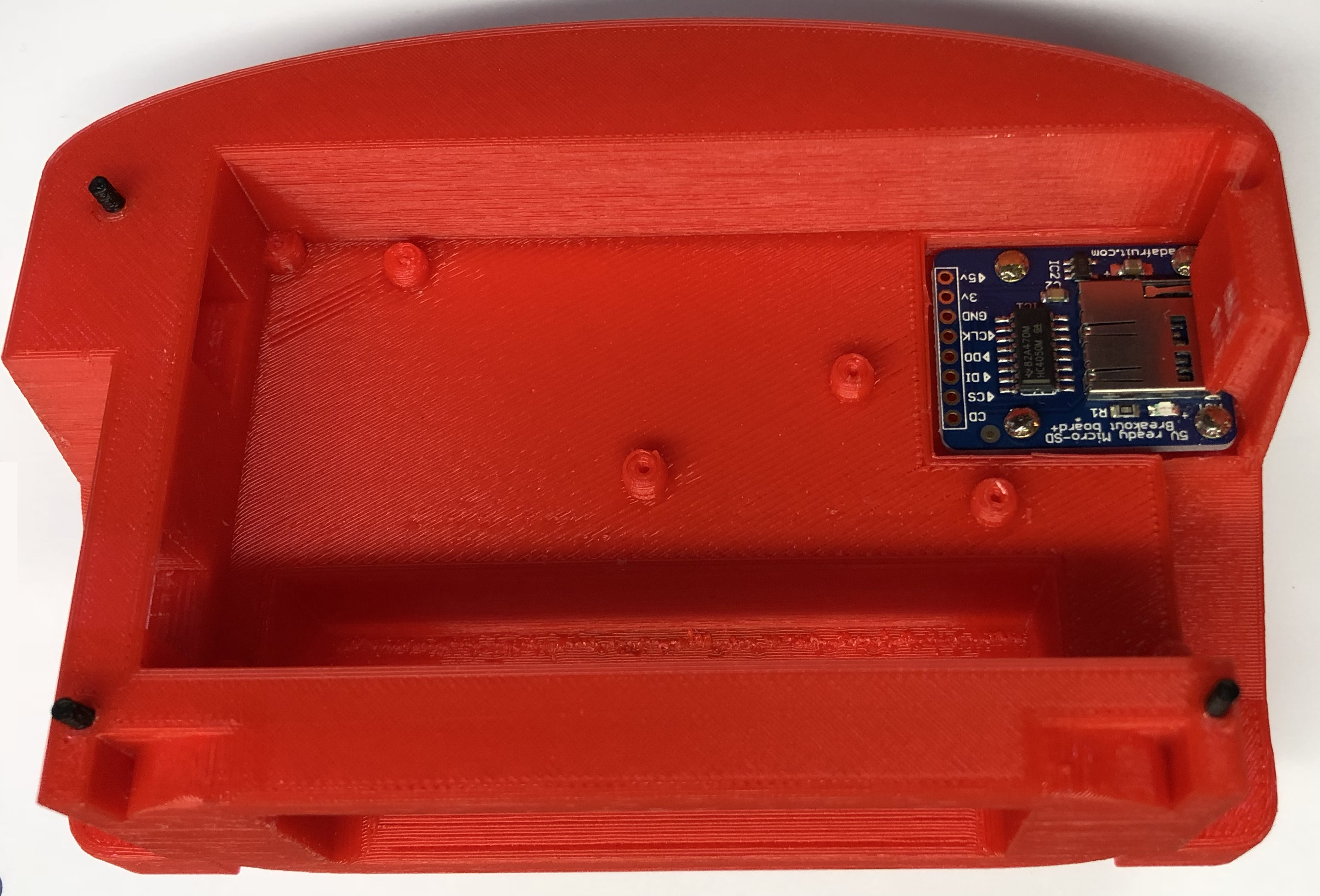
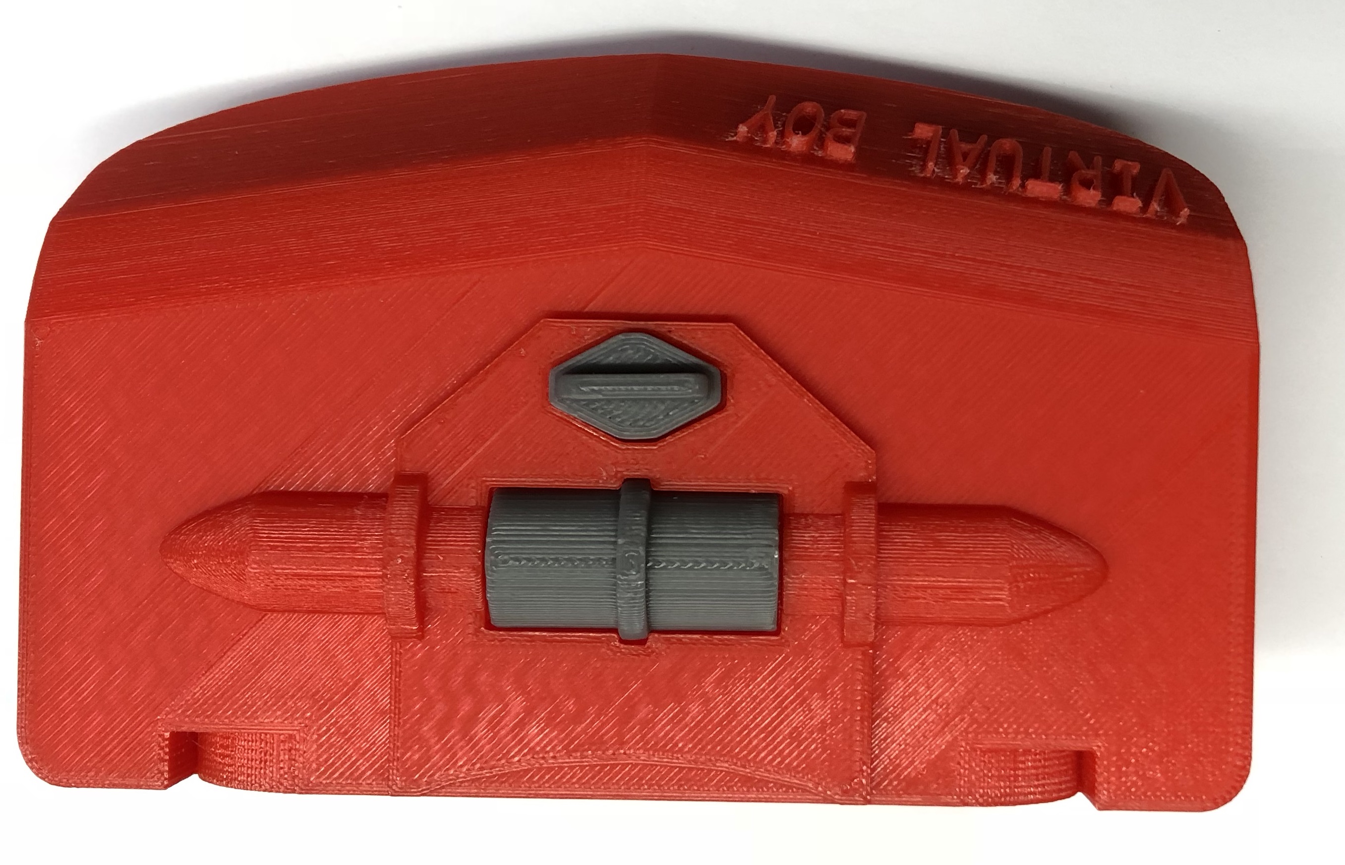
Ignore the black alignment posts for now. Those need to be put into place after a few of the other pieces go on. Once the SD card board is in then we can start attaching the 3D printed knob parts and ears. Flip the large red top enclosure over and glue in the gray knobs using Loctite 401. Spread some glue into the channels in the red top enclosure and snap the gray parts in place. Hold for 20 seconds.
The next thing is to attach the ears. Make sure you did that fit check on these ears. You may need to trim the insert holes as well as some of the borders of the ears themselves to get a cleaner fit. Place some Loctite 401 glue on the red enclosure of one ear and then snap and hold the black ear in place. Repeat for the other side.
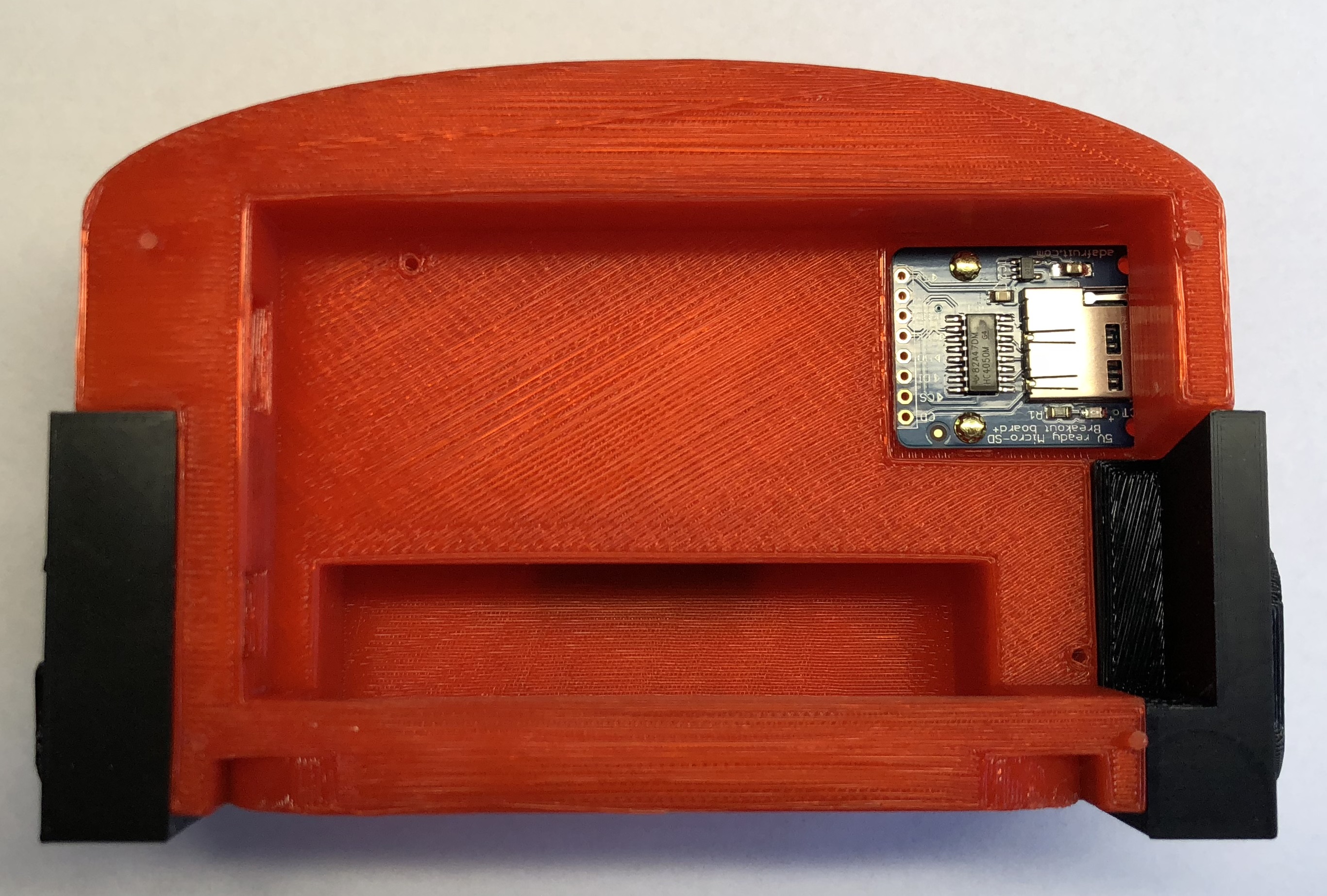
You can now insert those small black alignment posts that were shown in the first image above. This can also wait until the bottom is ready if you’re worried you may snap these off. They’re quite thin so be careful with them. Dab Loctite 401 into the top red enclosure holes and insert the pegs one at a time. Make sure they’re vertical. You may need to clean support material out of the holes first so do a fit check.
That will do it for the top 3D printed assembly for now. Next we’ll do some electronics prep work and fit checks.
Electronics
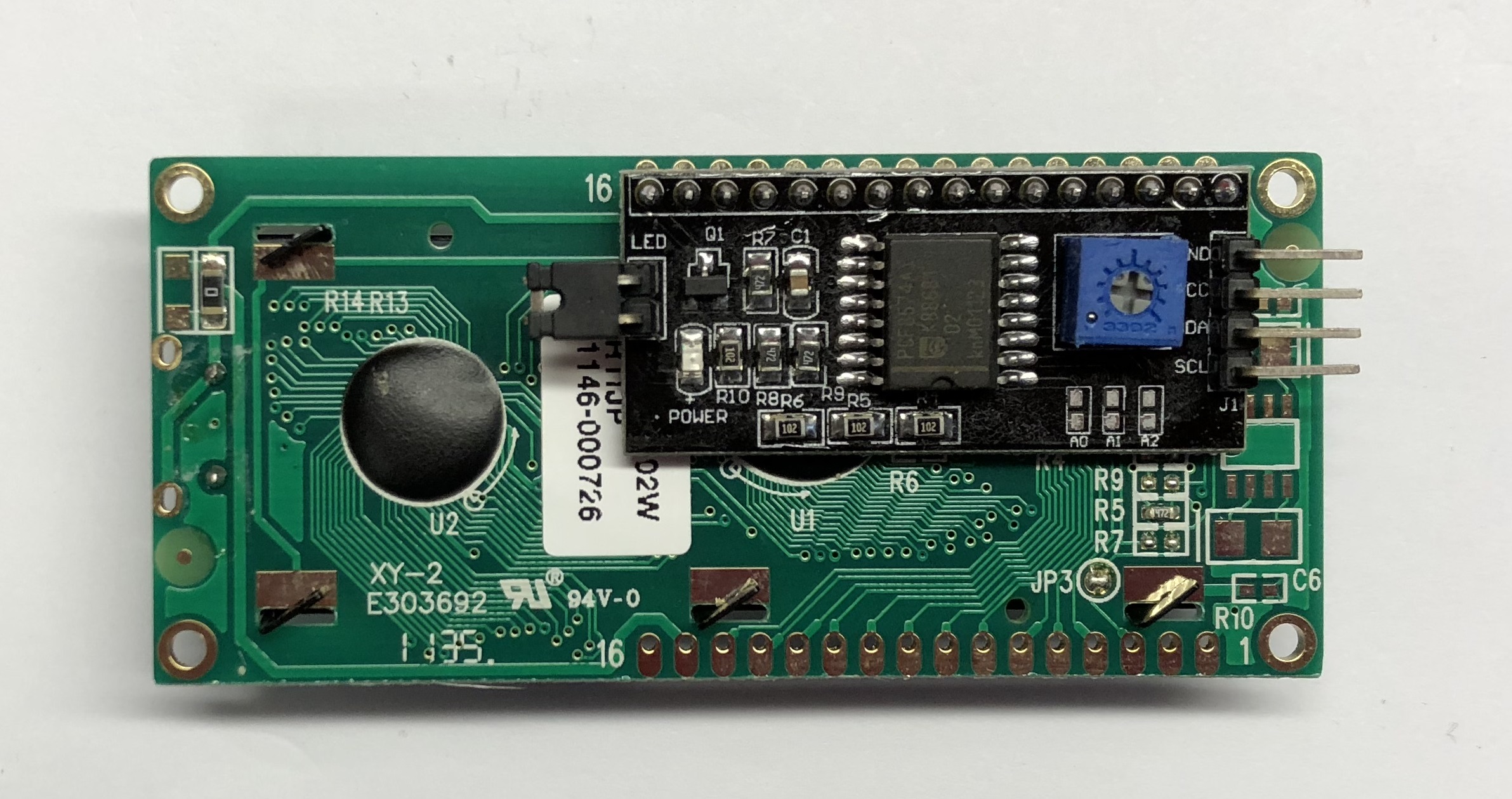
This is where the bulk of the assembly will occur. You’ll need to be handy with a soldering iron, wire cutters, and wire strippers. Lets start with the prep work. You’ll want to assembly the I2C-LCD backpack onto the back of the LCD first and attach some wires. Make sure to cut the I2C-LCD backpack headers short so that they don’t poke past the LCD PCB itself, otherwise the LCD won’t fit flat in the enclosure. I don’t show an example here but basically you want that front surface around the LCD to be as flat as possible. Trim the I2C-LCD VCC,GND,SCL,SDA leads in half otherwise they’ll bump into the housing. Then attach some ~6″ long wires to the I2C-LCD backpack leads to be used later. See the pic below (leads still long and wires not shown. See next figure).
Next do a fit check of the LCD into the top red enclosure to make sure everything will fit and the wires are long enough to be trimmed and routed later.
Atmega2560 and Programming
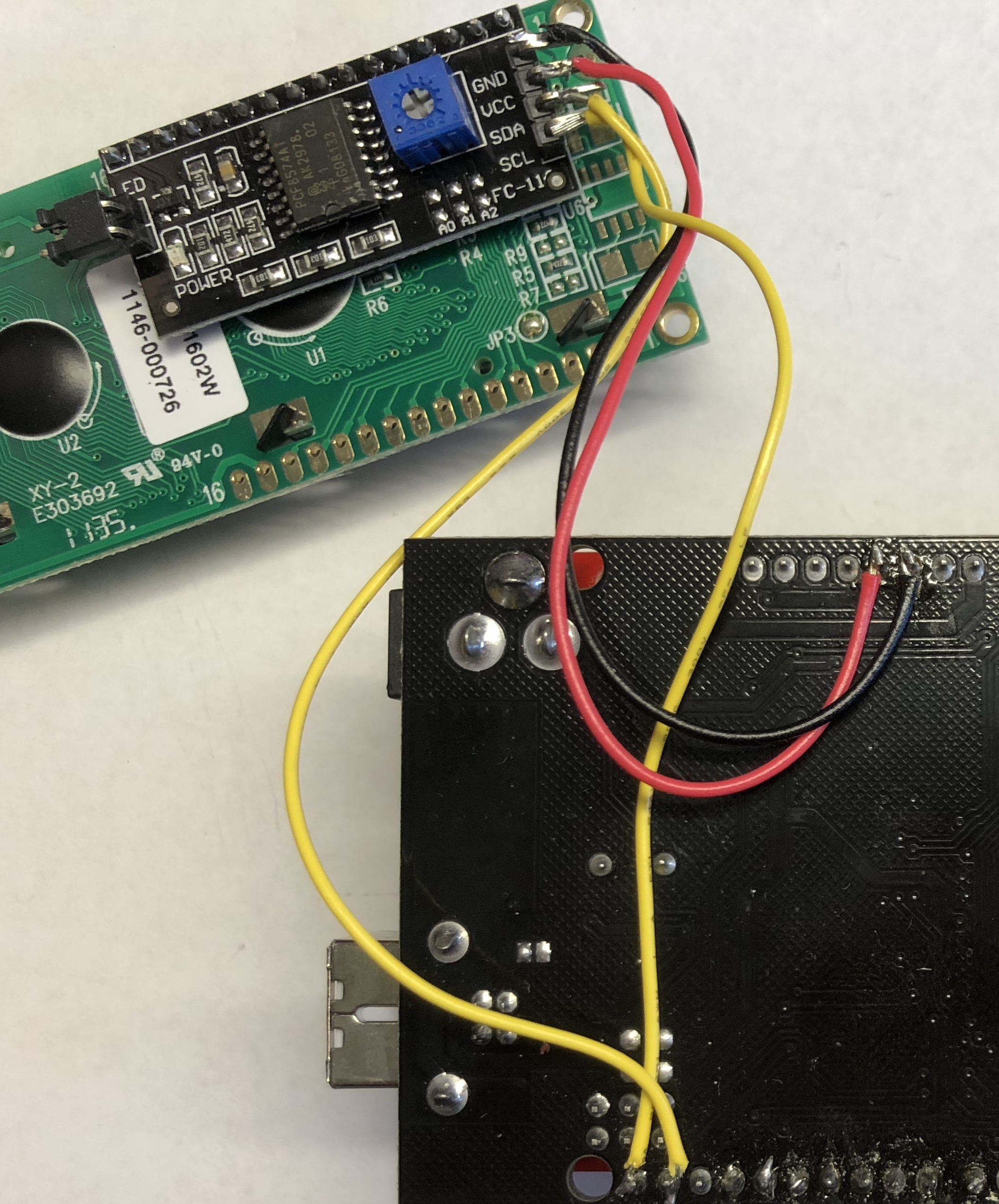
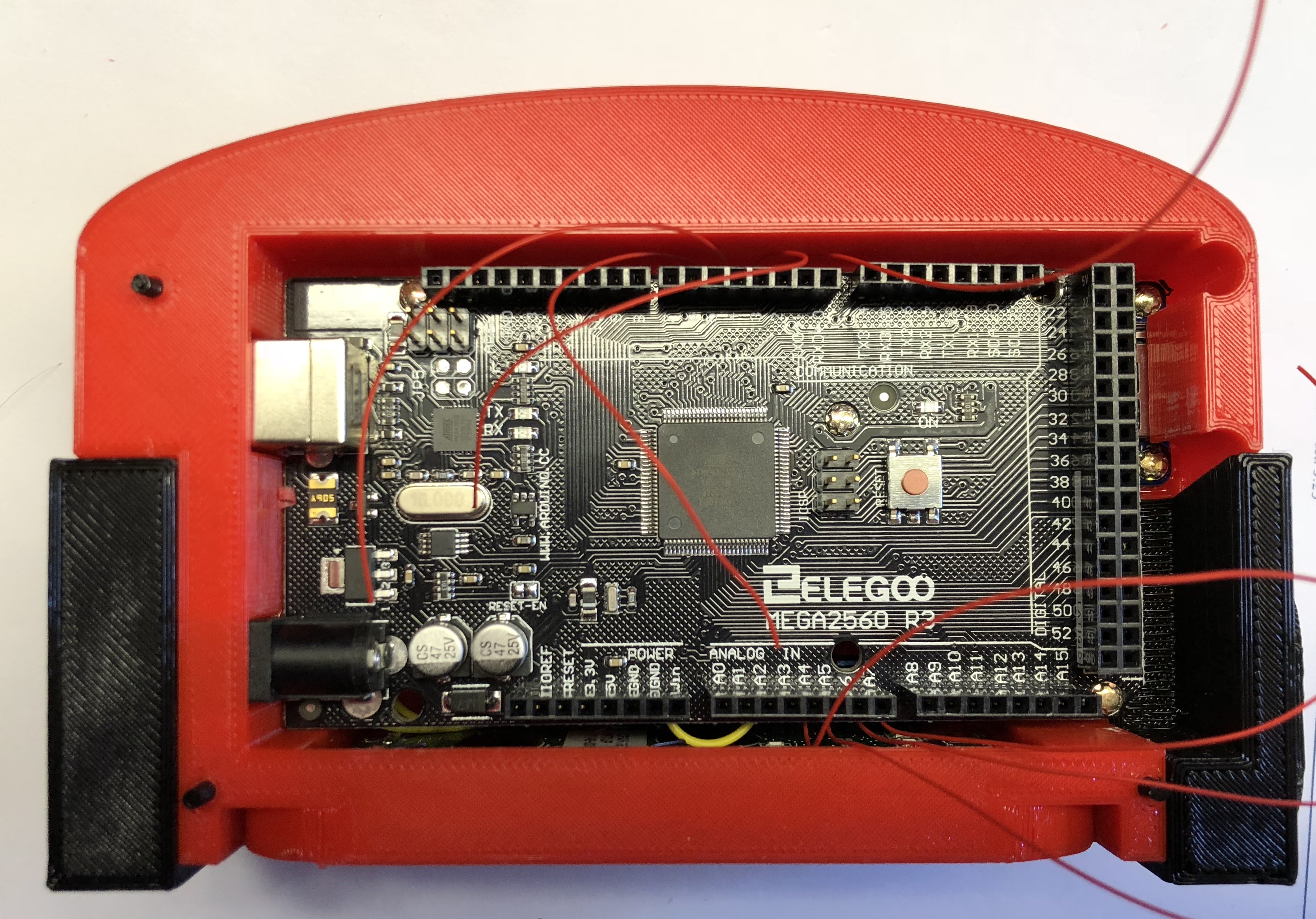
Now lets fit check the Arduino atmega2560 R3 board. Insert the board into the top enclosure and make sure holes line up and nothing is preventing it from being inserted. Trim 3D printed material or clean if needed. Tip on the mounting holes: its better to leave the material in the holes and keep them tight. They’ll open up when you screw in the small VB security screws later. Now we’ll attach the LCD to the Arduino board as shown below. Attach the wires to the back side of the atmega board as shown. Pay attention to connect SCL, SDA correctly as well as the power lines
This is a good spot to stop and program the atmega2560 board and adjust LCD contrast. I won’t go into detail here on the programming. You’ll need the firmware file from me as I haven’t released the source code yet. Program the atmega2560 board. It should light up the LCD after programming. Adjust the LCD contrast via the small blue pot on the back of the I2C-LCD board so the LCD has nice contrast.
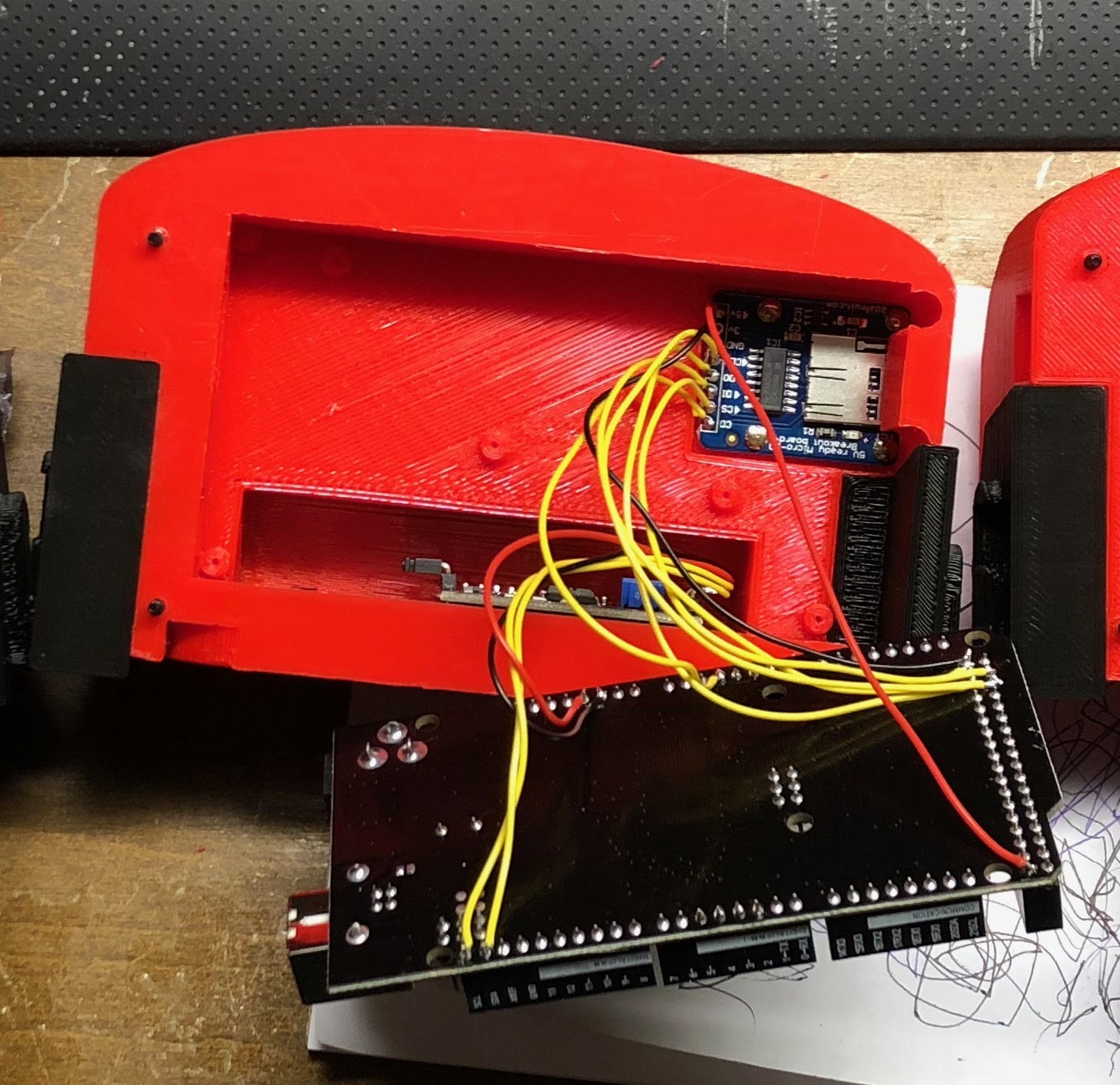
Next attach some long 30AWG sold core jumper wire to the 8 positions shown. These are needed for the custom VB motherboard connector PCB in order to modify some pinouts for the LCD and SD card board. The LCD and SD card board were not apart of the original design when I designed this custom PCB so there are jumpers. Make these wires about 8″ long or so. They’ll be trimmed short later.
SD Card and Epoxy
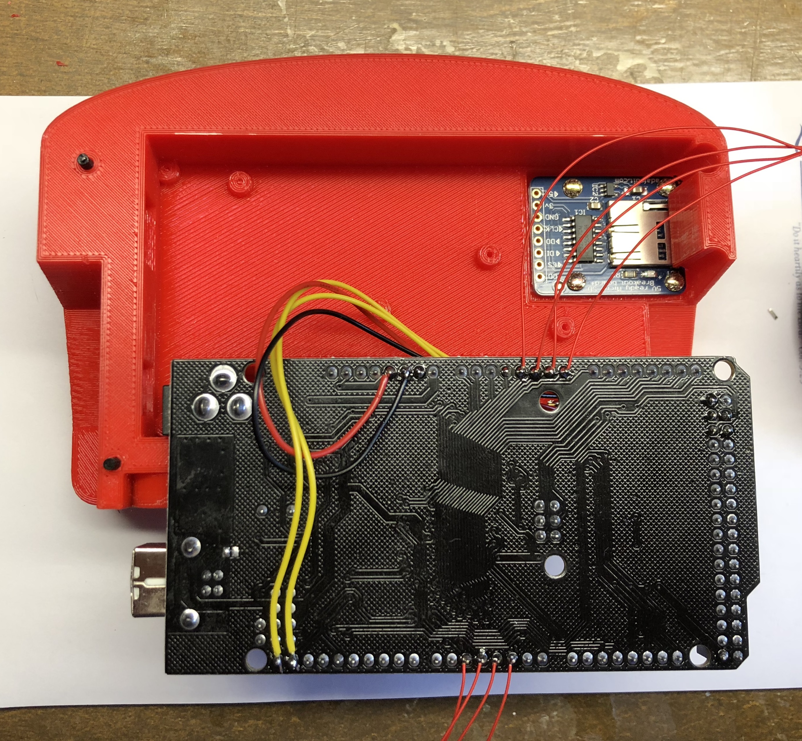
Now its time to attach long leads to the SD card board and wire them to the atmega2560. Wire as shown in the image below. Make the leads long so that you can flip all the pieces in and assembly them. About 6″ or so but you’ll need to confirm the exact length yourself.
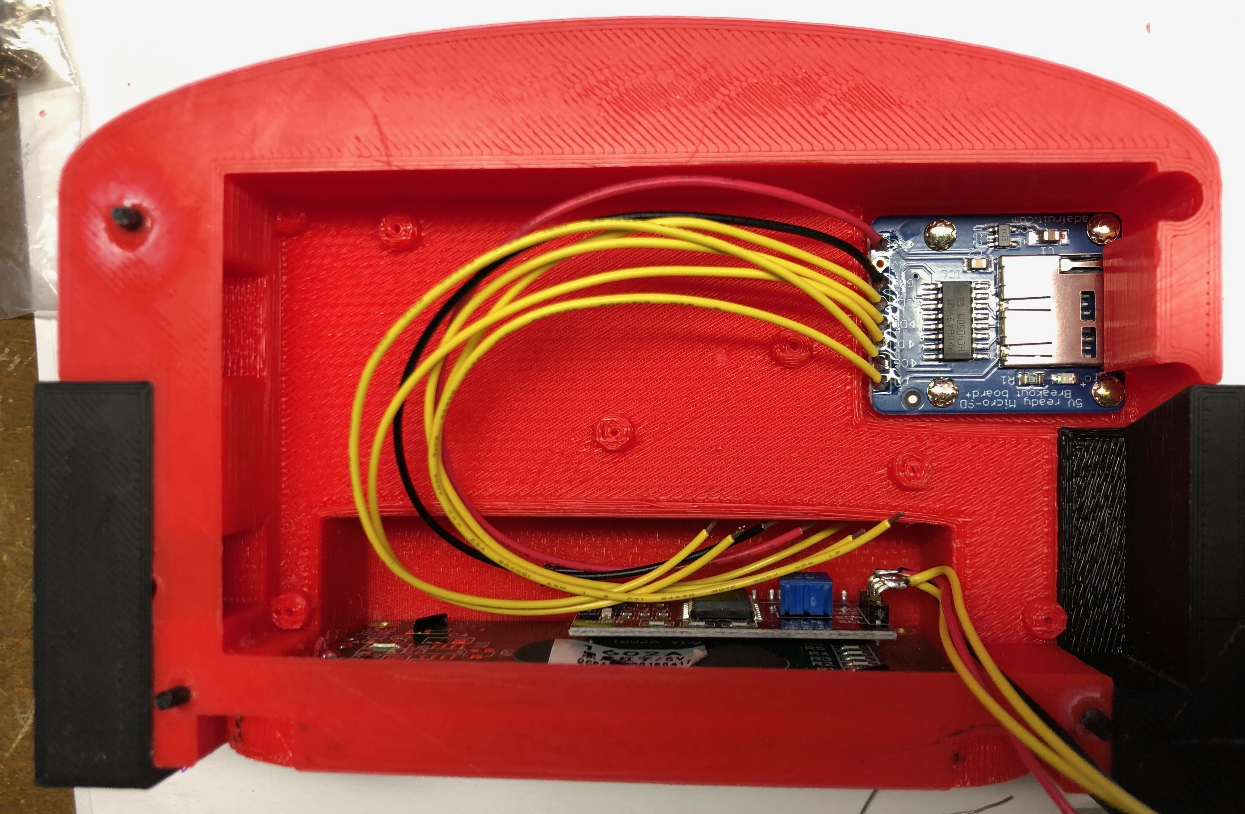
Next insert the LCD back into the top enclosure and put two small VB security screws into the bottom holes. There’s just enough room to get them in. With the LCD and SD card in place, move the atmega2560 board out of the way just enough so some DP100 epoxy and be beaded across to top edge of the LCD inside the housing, as well as around the perimeter of the SD card board. These makes sure they’re nice and secure. BECAREFUL not to leak epoxy into the SD card slot!!
Now put the atmega2560 board into place and screw in 3 of the small VB security screws. don’t tighten them all down at once. Get them in place to help hold the board and then tighten them down. Make sure the routing of the LCD board wires and SD card board wires are not being pinched or pushing up on the board. There’s just enough clearance to get everything in there and properly seated. Carefully fold the small solid core jumper wires upwards paying attention to space them properly so you can remember where they go. You’ll need to fold them over later and attach them to the top board.
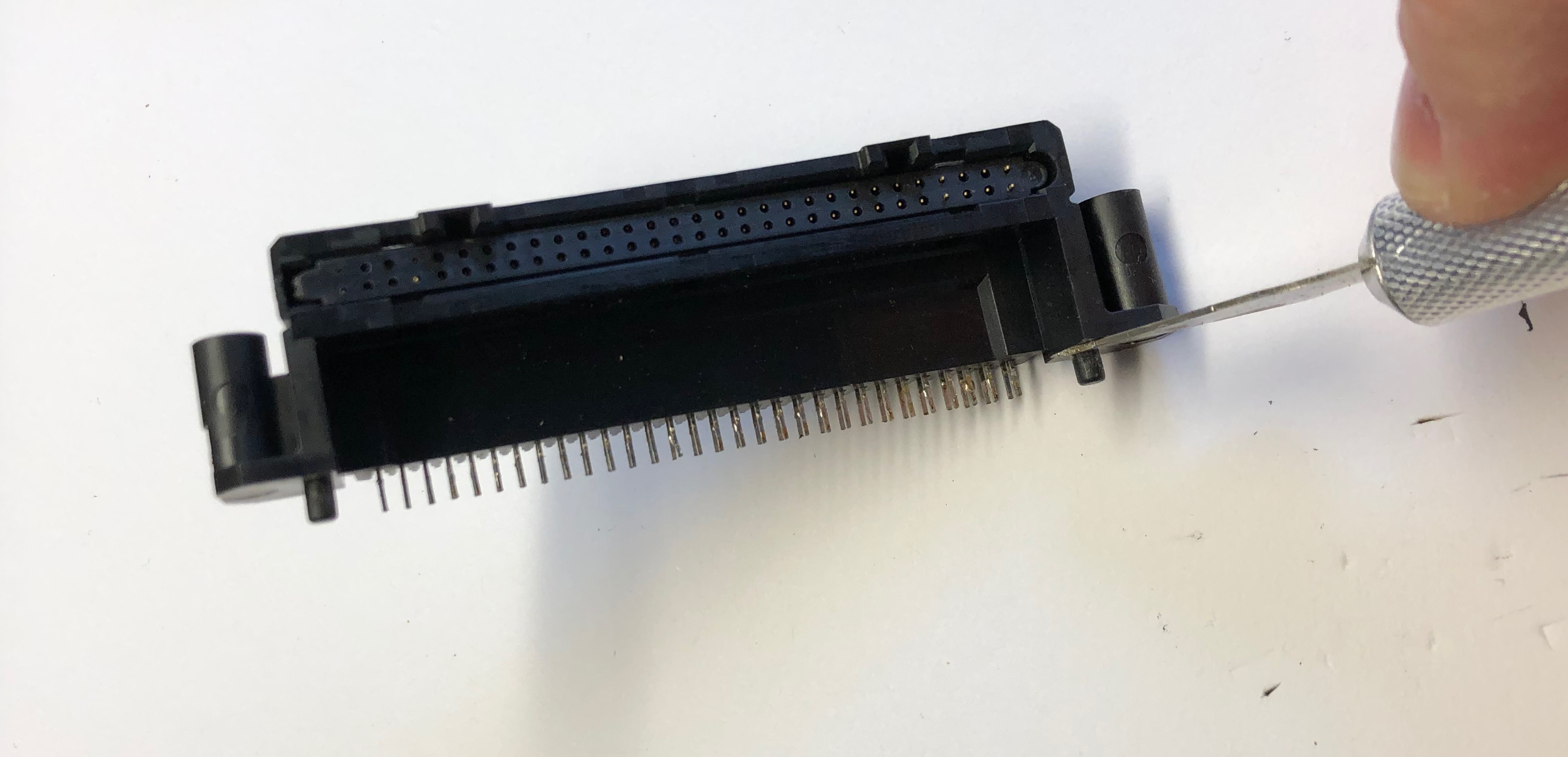
Make sure everything is tightened down at this point before continuing. Now you’ll need to take your VB motherboard and some solder wick and remove the connector from the board. Once removed you’ll need to trim the black posts from the bottom flat with an Xacto blade. Make sure they’re flat otherwise the connector won’t sit flat on the custom PCB. It takes some patience but it will come loose with solder wick and some care. Don’t damage the connector!
VB Motherboard Connector
Then attach the VB motherboard connector to the red custom PCB. Load the small 2.2uF caps on the custom PCB C1 and C2 locations as well. The picture below (missing caps) shows the custom PCB with connector, capacitor locations, and even where the jumper wires need to go. You’ll need to insert 0.1″ headers into the atmega2560 board where it connects to this board. Don’t insert header pins where the jumper wires go. Follow this picture VERY carefully otherwise your programmer will scramble the data! Trim and fold the jumper wires as needed and solder everything into place.
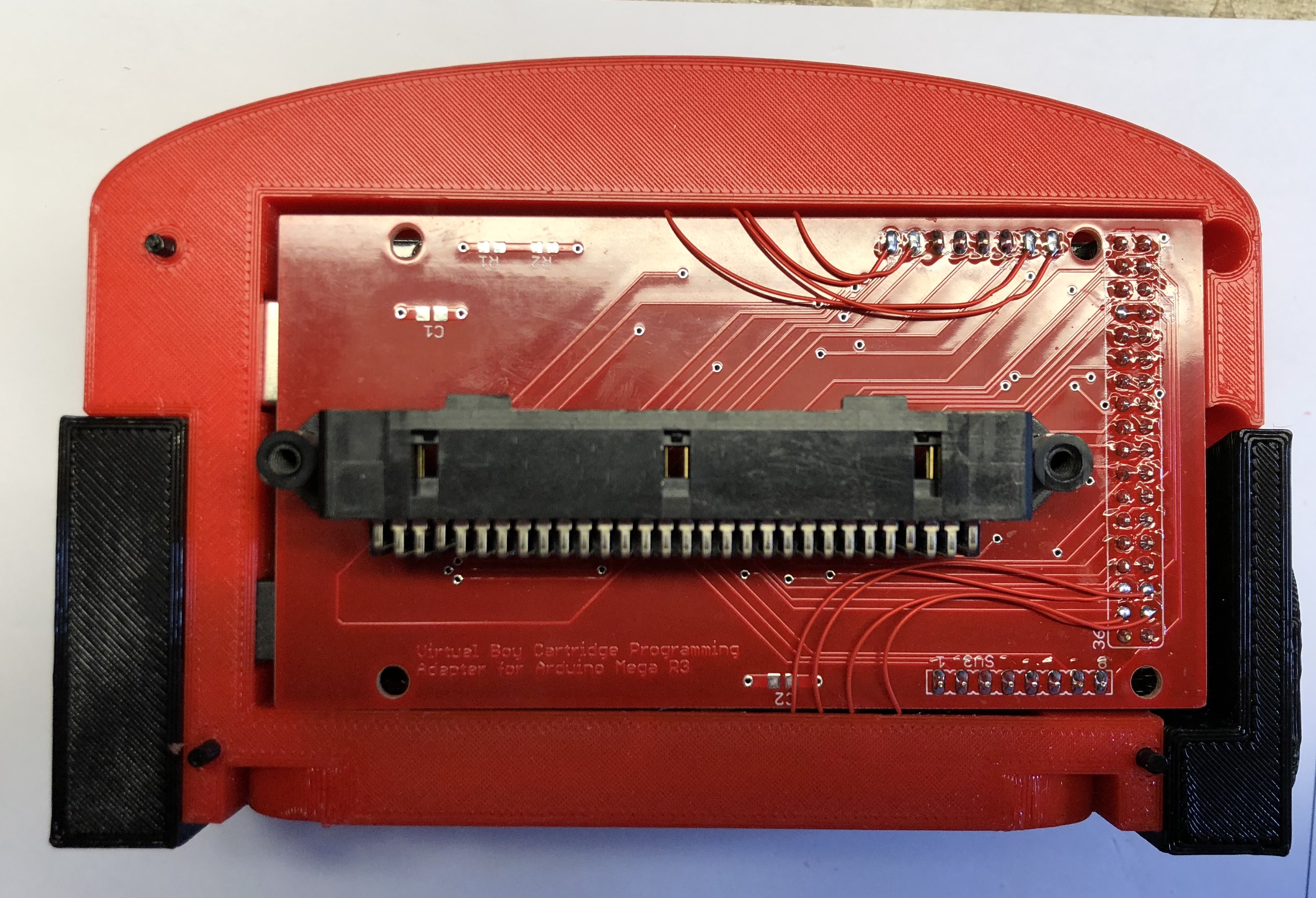
Electronics are done!!!
Final Programming Check
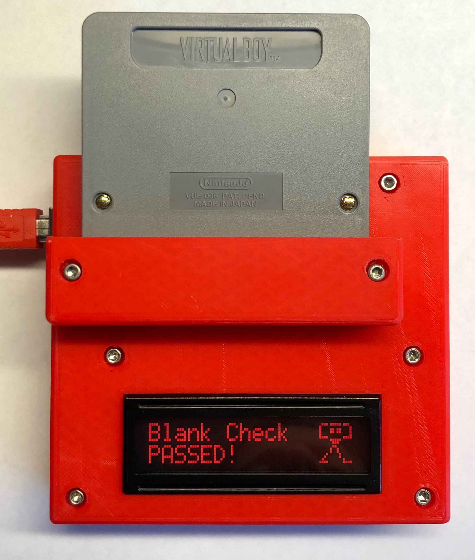
At this point you’ll want to do a final programmer check. Insert an SD card with a ROM file and program a 16Mbit or 128Mbit cart. Refer to the VB cart programmer main page for more details. This will be the final check prior to sealing up the unit. Make sure everything checks out so spend some time testing here if needed. Once the bottom is put on its near impossible to take back apart.
Final Button Up and Letters
Do a fit check at this point with the bottom black cover and make sure the bottom holes line up. Larger VB security screws will be used here to attach the bottom piece along with some Loctite 401. Those alignment pins will help guide us here so if you didn’t insert them earlier, do it now.
I don’t have good pictures for documentation here and will add them in the future. A bead of Loctite 401 is placed around the edge of the atmega2560 board on the 3D printed material side. Then slide on the bottom black piece but don’t let it touch the glue yet! Put in the long VB security screws and make sure you can start them threading into the holes. You may have to gently nudge things into place. If the screws can be started then push the bottom into place and very quickly tighten down the security screws.
The main assembly is now complete! Flip the unit over so you can see the front VB letters. Take a black sharpie or black paint pen and go over the letters carefully. If using sharpie you’ll need about 4 passes to make it nice and sharp.
That’s it!! With the entire assembly done now insert a cart and make sure its all up and running. It’s a long 2 hours process but the final product is quite unique!
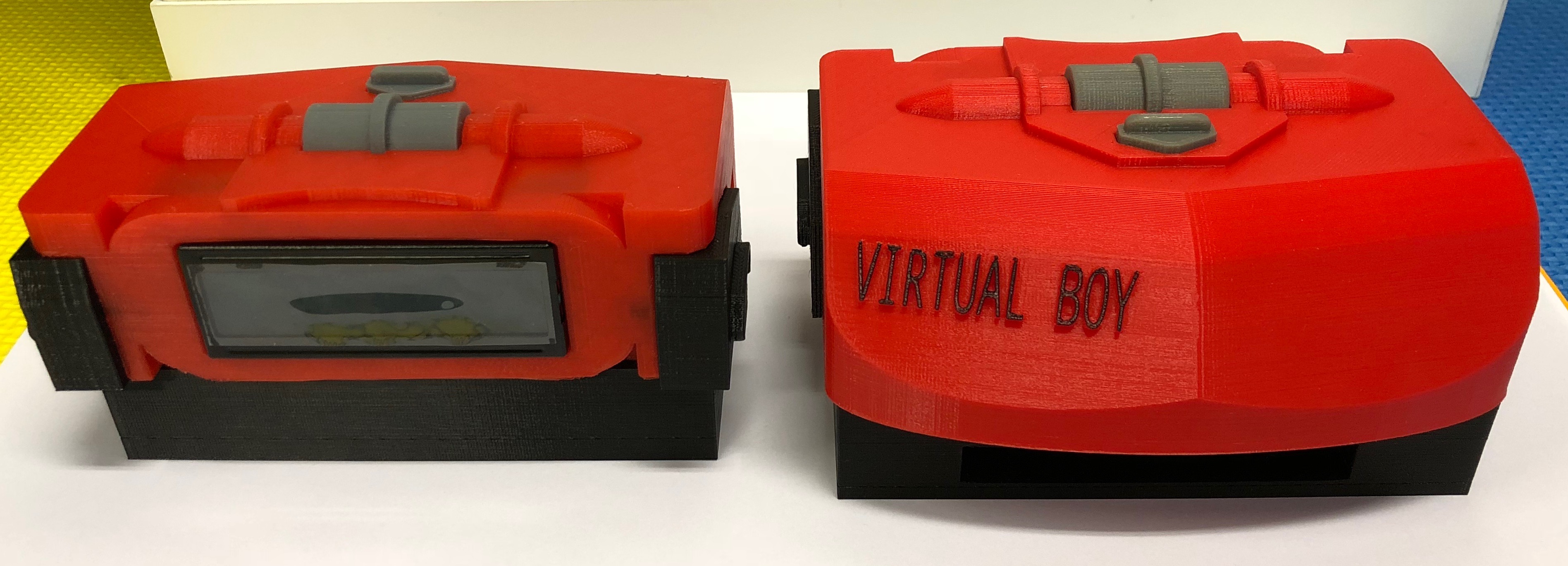
Someone was also kind enough to build a simple enclosure version which is faster to build. Here’s a picture of it:
If you’d like the design files for the enclosure version they’re here: VBProgramTop.stl, VBProgramBase.stl, and VBProgramCap.stl.
Here’s also the latest hex file to program the atmega2560 if you’re trying to build one yourself!
And finally, I’m releasing the VB mini 3D print design files as well. Have fun!
VBMiniTop.stl, and VBMiniBottom.stl, and VBMiniPosts.stl, and VBMiniSlider.stl, and VBMiniKnob.stl, and VBMiniLeftEar.stl, and VBMiniRightEar.stl
