 Mellott's VR
Power Glove Linkbox USB
July 2014
I’ve decided to make an updated Nintendo Power Glove linkbox after all these years. What can I say, I like my vintage VR gear. This linkbox is very similar to the original, electrically, except this time I adapted it to the stock NES connector and provided a USB output. I tried to keep the PCB as small as possible. The outer board dimensions are 30mm x 21mm. I’ve seen adapters like this online but it seems like a lot of them are no longer available or don’t work with the Power Glove. This adapter is for the Mattel Power Glove with the 7-pin NES connector. The current version of the PGLink2 will NOT work for the PAX/Famicom Power Gloves. If you’re interested in getting one of these PGLink2 boards, please contact me via my contact form.
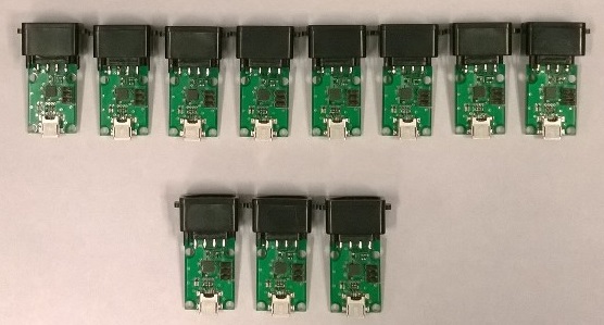
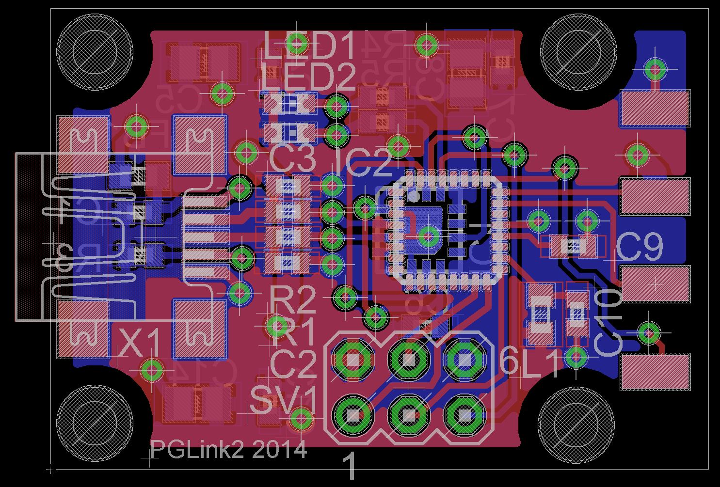
The PCB design is shown below. I had 100 PCBs made. I have built 12 units. The NES connectors are getting more difficult to get so currently that’s all I can build. The boards do have 1 small mod to change the input pin that the Power Glove data comes in on. I swapped a pin during routing to make it easier and turns out that pin was analog only so I had to change it. Not too big a deal but I never like to see blue wires on my designs. Oh well…
PGLink2 Design files v1_2 are here. Use v1_2 for atmega88pa processor. If you load a larger atmega328p processor you can use PGLink2 Design files v1_4 which have a few more help menu commands, as well as stores the filter variables in EEPROM. Version 1.4 files are here. The design files include EagleCad schematics, board files, AVR Studio 4 firmware files, and PCB gerbers. These files already implement the mod mentioned above so they’re up to date.
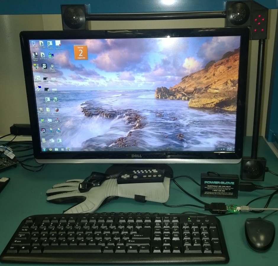
Shown below is the first picture of my power glove connected to a PC via USB using the PGLink2. The new board is powering the glove and is able to stream data to the computer. You can see the PGLink2 in the bottom right hand corner. It’s the green board between the USB cable and the Power Glove.
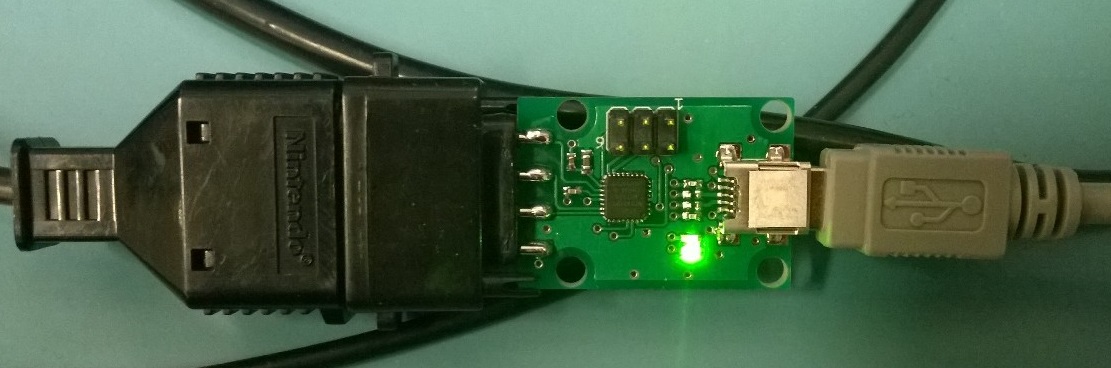
Here’s a closer look.
Firmware is up and running. Currently it runs over USB via a Virtual COM port at 115.2kbaud, 8,N,1 with even parity. What I also like about this USB approach is that I don’t need any external power adapter. There are commands to change from ASCII data to binary data (BIN), toggle data continous mode (CONT), print a command menu (HELP), print the FW version (VER, useful as a COM link test), issue a Power Glove reset pulse (RESET), and issue the Power Glove High Resolution command (HI_RES). There are some filtering commands as well that aren’t printed out via HELP. If you read through the firmware code you can see how to set them. Commands are issued through a terminal program in all capital letters. The power up default state is to have the Power Glove streaming data in an human readable ASCII format, as shown below.
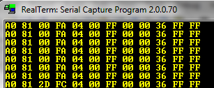
Binary Data from Power Glove. |
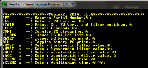
Help menu showing commands. |
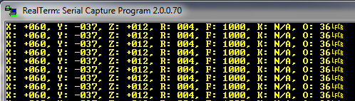
ASCII Data from Power Glove. |
The timing very closely follows the Power Glove timing chart on my site. I have a few mods but it’s more or less the same. There’s lots of talk online about some of these numbers being reduced or changed. Many of them can be but the glove is less stable. The firmware I’ve provided on this page represents a couple days of determining what makes the glove the most stable and repeatable. For example, you can run the glove update rate up to 25Hz before it crashes but it’s only stable at 20Hz or lower. Clock period can also be made shorter but why bother, the dominant time is a delay needed for the glove to get ready to send the next 12 byte packet. I’ve placed plenty of comments and notes in the firmware to explain what’s going on so feel free to experiment yourself.
The format of the output data is {header,x,y,z,rot,fingers,keys,0,0,occlusion,FF,FF}. This is of course for the high resolution mode which reports absolute position. The current PGLink2 board will not support anything else other than high resolution mode. At power up the glove is put in this mode or you can issue the HI_RES command in the terminal window. If you enter one of the other programs according to the Power Glove manual, the PGLink2 output is undefined. I was going to write up some documentation on the Power Glove data format but really it’s all in the firmware code. Please refer to that for more detail.
I’ve also updated the Power Glove files page with some old articles on the Power Glove. One of these articles is the original BYTE magazine article which showed how to modify the Nintendo Power Glove to connect to the parallel port of a computer. This article sparked people’s imaginations around the world.
Below is a video of a hand model being controlled in WorldViz Vizard. Vizard is reading data from the Power Glove through the PGLink2 board and using it to update the hand position and finger angle using a slightly modified hand.py file. It’s really cool to see the Power Glove being used in a current VR environment! It would be even better to model the Power Glove in WorldViz Vizard and use it as the hand model. This was tested in WorldViz Vizard 5 beta. Not sure if it works in other Vizard versions.
You can download my WorldViz Vizard Power Glove demo code here. I added a function to the standard Vizard hand.py to allow the fingers to be set by passing degrees for each finger tip. Therefore the hand.py file is renamed handPG.py as to not conflict with the original. You’ll also need pyserial along with these Vizard files to run the demo code. My Power Glove code then reads the PG data and updates that function.
I have started a Vizard sensor plugin extension but it’s a bit buggy at the moment so I’m going to hold onto it for now. Once I’ve had the chance to iron out some issues I’ll post it here.
If you want you can add some Vizard grab functions to interact with objects within the environment. Have fun!!
